©2014 FIRECRACKER™GUW ALL RIGHTS RESERVED
Auger system construction
(Click to enlarge photo)
Once I had established that the principle of my design of auger would work I then had to construct something that could reliably do the job. The hopper was going to be a 205 litre oil-drum so I didn't want the auger to be too far off the ground. Also, because I was going to use the boiler from my old oil-fired system, I was limited for height due to the design of the front panel on the boiler. Note that a few inches of auger sticks out from the front of the fuel-tube, this will rotate inside the burner-head itself to deliver fuel just above the air-holes. The central auger tube is 1 inch diameter (25mm) and the fuel-tube itself is 3 inch diameter (75mm). If you are going to use low-grade wood-chips and there is the possibility of any larger lumps of wood getting through, then I suggest you use a larger diameter fuel-tube. Any blockage with this type of auger usually ends with a highly compacted fuel-tube that can take hours to sort out.
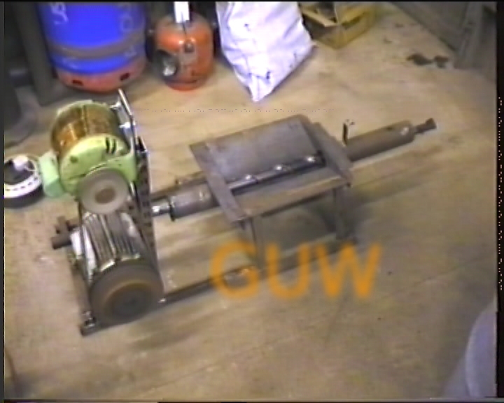
The oil-drum will sit above the pan in the centre and you can see the auger at the bottom. The gearbox is from an old conveyor-belt, courtesy of the scrap-man, and is driven by the green single-phase motor at the top. The original three-phase motor had to remain in place because it was an integral part of the gearbox but would not be connected to the electric supply. There are v-belts between the two motors.
If you are doing anything similar please take care. Once the shaft-speed is stepped down through the gearbox the auger turns very slowly indeed (between 20-60 RPM) and that means there is massive torque. It is vital to ensure that the system is made in such a way that no hands, pets or anything other than fuel can get neat the auger or its drive-train.
©2014 FIRECRACKER™GUW ALL RIGHTS RESERVED